FAQ
Below is a list of the most frequently asked questions we get here at Kaz Technologies. Hopefully you will find your answer here. If not, send an email to jess@kaztechnologies.com, and we will get you the information you need.

Below is a list of the most frequently asked questions we get here at Kaz Technologies. Hopefully you will find your answer here. If not, send an email to jess@kaztechnologies.com, and we will get you the information you need.
For ordering questions, please e-mail us at Jess@kaztechnologies.com.
Cost of shipping is based on weight, distance and time. After selecting your products in our online store, you can insert your location and select your shipping method; which will tell you shipping cost. Time is based on your distance from our shipping location, how quickly do you want your order and how much you are willing to pay. An extra week must be allowed when ordering shocks custom built to your specifications.
The Kaz Tech products are only available through Kaz Technologies located in the United States. However, we ship to all parts of the world.
Sorry. At this time we are not able to offer any discount or sponsorships to any team. However, our technical assistance is available to any team without charge.
Yes, all products are available in our online store.
Shock drawings and other technical information can be found under downloads.
Yes, service tech information can be provided.
All the information about our products can be found by clicking on the products themselves. If you need additional help, please send an email to jess@kaztechnologies.com.
We accept Visa and MasterCard, or you can pay by check or bank transfer. However, there is a $40.00 bank transfer fee. No products are built, shipped or serviced until we receive full payment.
We warranty all our products against manufacturing defects. We will gladly replace them if you find any issues before you install them on your car. However, like all racing products, we do not supervise the installation or use of our products, therefore we are not responsible for any breakage due to improper installation or use.
This is the million dollar question. Unfortunately, there is not one technique or response to this question that is the correct answer. There are nearly unlimited options when it comes to damping and the proper result in each application is as unique as the car and the team that designed it. It is imperative to understand that proper damping design is not strictly driven by mechanical specifications such as mass and spring rates, but also by the relative importance of overall car properties such as handling, grip, and aerodynamics. There are many compromises to be made and as a design engineer you know your car better than anyone else, and thus you are the one most qualified to make these decisions. All you need is a little fundamental understanding so that not only will you have a properly damped race car, but you will also know why.
This is where the journey begins. The process of designing damping starts with a basic understanding of how damping affects a dynamic system. This understanding will allow you to know what it is you can and cannot do with shocks in general. Once you get the basic overview you must apply that knowledge to the goals and purpose of your car design. For example, you can target damping to items such as aerodynamics, mechanical grip, and handling and you can target each in pitch, roll, heave, and warp but you cannot optimize all things at one time. It is your decision on the items of importance and relative compromising of each.
First, it is important to understand vehicle dynamics and especially concepts pertaining to tires, grip, corner loading, chassis motion, and transient handling behaviors. Information covering these topics is widely available online and in print. This includes items, such as text books, that are not vehicle specific but still cover the important engineering principles. Think statics, kinetics, kinematics, and vibrations.
Second, put your engineering tools to work. You can start with the most basic analysis which requires nothing more than applying fundamental dynamics and vibrations. If you simplify your system, or partial system, as a linear 1 degree-of-freedom (DOF) mass, spring , damper system, and perform some analysis you can identify most all basic parameters commonly associated with suspensions and damping.
The free body diagram and equation of motion for the 1 DOF system which you should already know is:


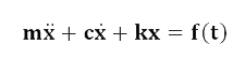
where m is the system mass, c is the actual damping coefficient, k is the spring rate, x is displacement of the mass as a function of time, and f(t) is the external force acting on the mass as a function of time.
From solving this simple 1 DOF model all the following important equations can be derived:
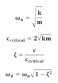
where ωn is the system’s undamped natural frequency, ωd is the system’s damped natural frequency, ζ is the system’s damping ratio, and ccritical is the system’s critical damping coefficient.
These equations constitute simple yet valuable information about a system that summarizes some general and specific behaviors. You should make sure you understand how the normalized parameters of natural frequencies and damping ratios describe a simple system.
It depends. The basic 1 DOF model, and the parameters derived from it, is full of assumptions and simplifications. However, it still provides system descriptions that are accurate under the assumptions. It is up to you to determine if the simplification of a 1 DOF model provides answers that are close enough for your application. Understanding assumptions and simplifications is a large part of the engineering problem solving process.
For example, the model assumes linear damping coefficients and spring rates and thus the more linear your shock curves and wheel rates, the more accurate the model is. You could choose to use linear spring and damping rates purely for the ability to accurately predict your car’s behavior using the simple model. You also could choose to not to run linear rates and adjust your model for the more complex behavior. Yet another option is to run non-linear rates while using the linear model, understanding there are variances unaccounted for.
In the end, you want to design using engineering tools, get your expected behavior close enough, and finish tuning and tweaking while driving the car. The goal here is to be close to your desired behavior so track testing takes you from good to better and not bad to good.
The sky is the limit. A logical next step up is to create a 2 degree-of-freedom (DOF) model that includes unsprung mass and tire rates along with suspension wheel rates and the sprung mass. If you desired a very full model you can create a 7 DOF system that includes displacement of each corner’s unsprung mass as well as chassis heave, pitch, and roll. Even further you can begin incorporating non-linear parameters into your model for items such as damping and springing. It is your job as an engineer to know how far you need to go to get the results you require.
Generally, springs come first and damping comes second, although you should have an idea of what normalized damping you desire while designing wheel rates. Whether you design suspensions for grip, aerodynamics, handling, or something else, springs are arguably the most dominant component. Wheel rates determine a large part of the dynamic response as well as all of the steady state response. So the choice of spring rates is targeted to many items, none of which are actual damping rates. Once you know your masses, wheel rates, and something about your normalized damping target you can determine where you should be with actual damping rates.
Damping ratio (ζ) is a unitless, normalized parameter that summarizes the damped response of a 2nd order system. It is the ratio of actual damping to that which would be required for critical damping and it is the simplest way to summarize system damping with a single, concise term. While it is technically valid only for 2nd order, linear, time-invariant mass, spring, damper systems the simplification holds useful merit even as systems become more complex.
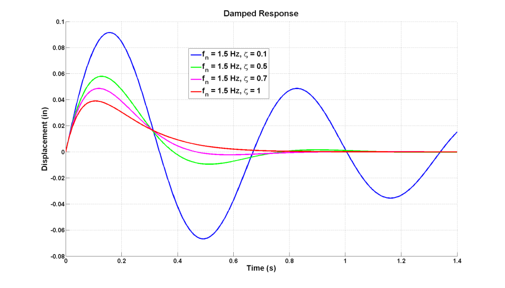
Since damping ratio is normalized to the relationship of system mass to system spring rate, all 1 DOF systems with the same damping ratio have the same characteristic damped response, regardless of the magnitude of the mass and spring rate. Damping ratios greater than 1 are termed over-damped, exactly 1 is termed critically damped, and less than 1 is termed under-damped. In the case of critically damped, the system response from an initial disturbance is a return to equilibrium without any overshoot or oscillations. In the over-damped case system response from an initial disturbance also returns to equilibrium with no overshoot or oscillations but will take more time. In the under-damped case system response from an initial disturbance returns to equilibrium after oscillating. The closer to 1 the under-damped case is, the less it will oscillate before returning to equilibrium and the closer to 0 the longer it will oscillate.
The figure below illustrates how different damping ratios affects a system as it responds to an initial disturbance.
Tip: Understanding damping ratios and its effect on system response is the key concept to designing damped response. Know what it would take to critically damp your car and know where you are in relation to that critically damped case.
Natural frequency is a normalized parameter often expressed in Hertz or radians per second that summarizes particular responses of an under-damped mass, spring, damper system. Similar to damping ratios, systems with identical natural frequencies will respond with identical behaviors to external inputs. There are two common but different types of natural frequencies, the undamped natural frequency and damped natural frequency. The undamped natural frequency of a system is the frequency at which the system would freely vibrate after a disturbance if it had no damping. The damped natural frequency is the frequency at which the system will freely vibrate including the effect of damping. Most often the term natural frequency is assumed to refer to the undamped natural frequency. The damped natural frequency is easily found using the undamped natural frequency and damping ratio.
A system may have as many natural frequencies as it has degrees-of-freedom (DOF). However, the most often applied calculation of natural frequency is only valid for a 2nd order, linear, 1 DOF system. However, this is still a useful simplification for more complex systems.
As a tool, natural frequency summarizes important, basic dynamic factors about a system such as bandwidth, resonant frequency, 90 degree phase point, and transmissibility. These types of factors, if understood, can then be correlated to car behavior. For instance, bandwidth and phase are general descriptions of how a car as a system will react to handling inputs and thus can characterize overall handling response. Fundamentals of transmissibility give a good indication of how mechanical grip may be affected with a spring or damping change. Cars built with matching natural frequencies (along with other similarities) tend to have similar behaviors and thus natural frequencies can be a good way to target a specific or known baseline.
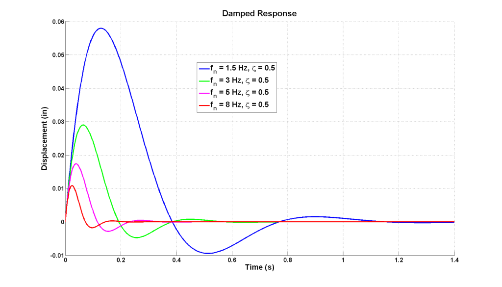
The figure below illustrates how systems with varying natural frequencies but identical damping ratios respond in time to the same initial disturbance.
Motion ratio describes the ratio between wheel travel and shock/spring travel. Convention at Kaz Technologies is to use shock travel divided by wheel travel. Motion ratios are rarely perfectly linear; however, for ease of use and simplicity we tend to treat it as linear. It is never a bad idea to build linearity into your motion ratio unless you have a specific reason not to do so. For the full picture of motion ratio and motion ratio variation, evaluate the slope of the shock travel versus wheel travel curve between min and max suspension travel.
Understanding motion ratio is imperative to achieving desired wheel rates. Because it is the wheel rate that ultimately determines how the car behaves, motion ratios are used to correct for the proper spring and damping rates in order to achieve the correct wheel rates. Do not miss this important step. The relationship describing motion ratio and the respective rates is:
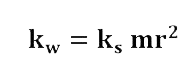
where kw is the wheel rate, mr is the motion ratio, and ks is the rate at the shock or spring. Important: Note that this equation holds for both spring and damping rates.
Similar to spring rate, a damping coefficient is the slope of a shock’s force versus velocity curve. It is expressed as force per unit of velocity. If damping is linear then the damping coefficient is a constant and fits nicely into basic linear models. If damping is not linear then the damping coefficient varies with velocity.
Wheel rate is the effective rate of the suspension between the wheel center and chassis. It is related to the rates of the installed springs and shocks by the motion ratio. It is wheel rates that are designed to control how the car pitches, rolls, heaves, and responds dynamically. Installed spring and shock rates are chosen so that when corrected by the motion ratio the desired wheel rates are achieved.
Transmissibility is another concept that summarizes particular behaviors of a mass, spring, damper system. It is the steady state amplitude ratio of output to input for a given frequency ratio and damping ratio. This amplitude ratio can be expressed in whatever units are of interest and most often will used as a measure of force transmitted or displacement transmitted. Transmissibility is a key concept to vibration isolation. One example of using this concept with respect to force is evaluating how a vibrating piece of equipment transmits force to the structure of a building and how this can be manipulated and reduced. A second example that would be concerned with transmitted displacement would be isolating sensitive equipment from a vibrating environment. Both of these concepts can also be extended to cars and race cars. The transmissibility plot below shows how amplitude ratio behaves as a function of frequency ratio for various damping ratios.
![]()
Frequency ratio is the ratio of the input excitation frequency to a system’s undamped natural frequency. Resonance for a damped system occurs near a frequency ratio of 1 and depends on the damping ratio. The frequency ratio of 1.414, the square root of 2, is the crossover point between amplification and attenuation at steady state and is clearly seen on a transmissibility plot. It is also worth noting that more damping decreases transmissibility at frequency ratios below 1.414 but increases transmissibility at frequency ratios above 1.414.
Resonance is the phenomenon that occurs when the steady state output of a system is at its maximum relative to a sinusoidal input. In the under-damped case this occurs when the input frequency is near the natural frequency of the system and thus the frequency ratio is close to a value of 1. When resonance occurs and very little damping is present, the input to output amplification can be extremely severe and quickly get to an out of control or damaging level. The basic relationship of resonance and damping is seen as the peaks on a transmissibility plot. Resonance is also easily identified as the peak on a Bode plot. Although traditional damping is not the only way to control resonance, it is extremely effective.
The resonant frequency of a 1 degree-of-freedom system with a damping ratio between 0 and 0.7 can be found from the following equation:
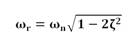
where ωr is the system’s resonant frequency, ωn is the system’s undamped natural frequency, and ζ is the system’s damping ratio.
Frequency may be measured in many different units. The most common units used are hertz (Hz), cycles per minute (cpm), and radians per second (rad/s or 1/s). Hertz is the unit of frequency in cycles per second. While rad/s is often a unit of angular velocity it may be extended to be a measurement of angular frequency when considering one complete cycle of a sine wave subtends 2π radians. Rad/s is an extremely critical base unit because of its fundamental requirement in deriving and solving most all equations associated with angular velocity or frequency. Therefore, rad/s are extremely important to the engineer while Hz is more intuitive for conversations and description.
![]()